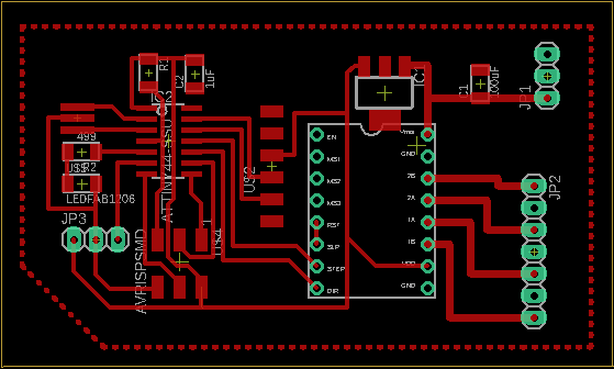
I designed an input/output board with inspiration from Adrián Torres's SAMDino who made his with the SAMD11C chip. What I mostly changed was that I based my board more on the SWD D11C programmer than Adrián's. Mostly because it resulted in a smaller board. Although, I really used much of Adrián's page both to make my programmer and to flash my board, as well as design it.
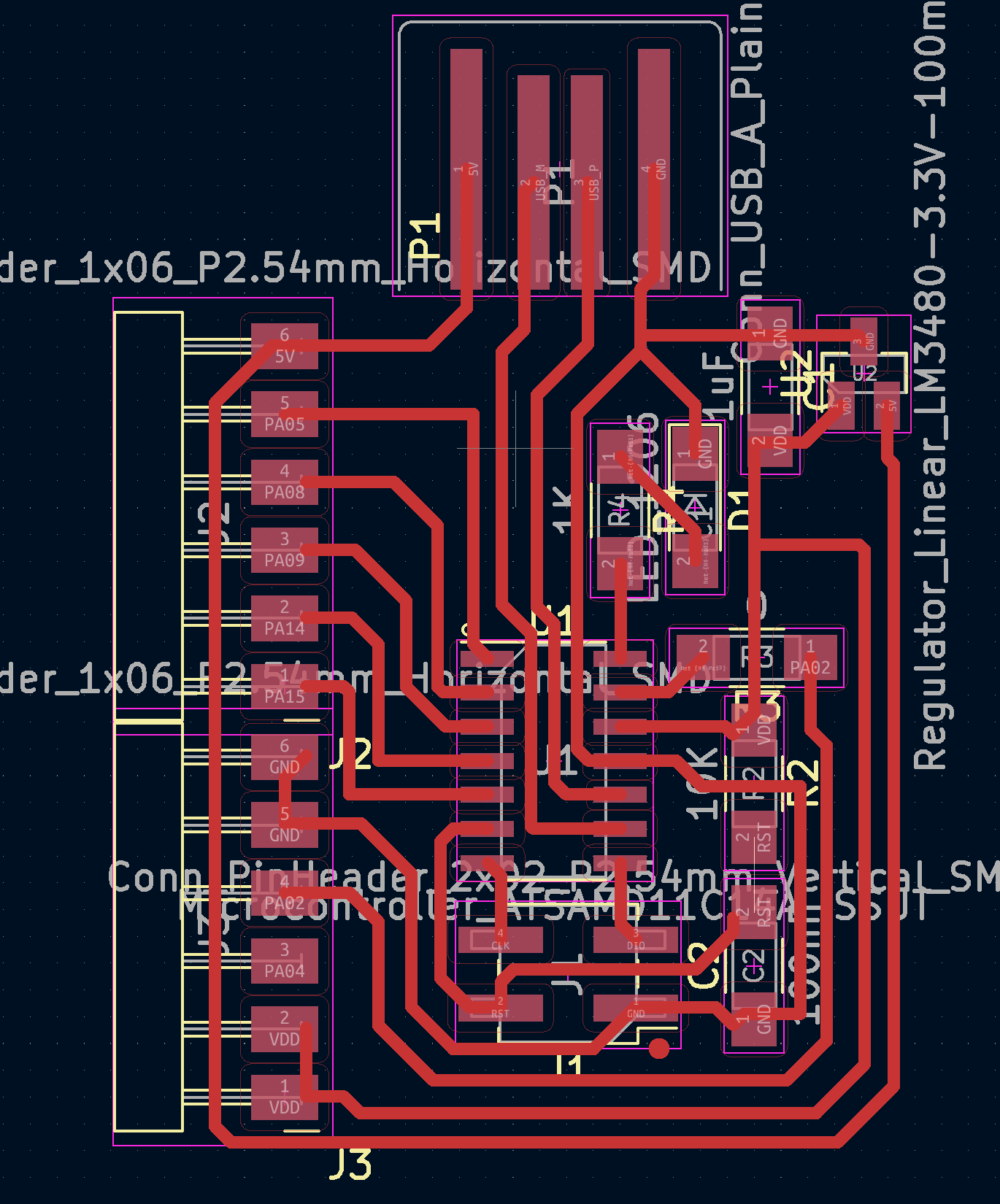
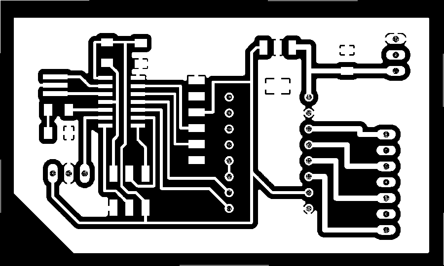
Here is the board design:
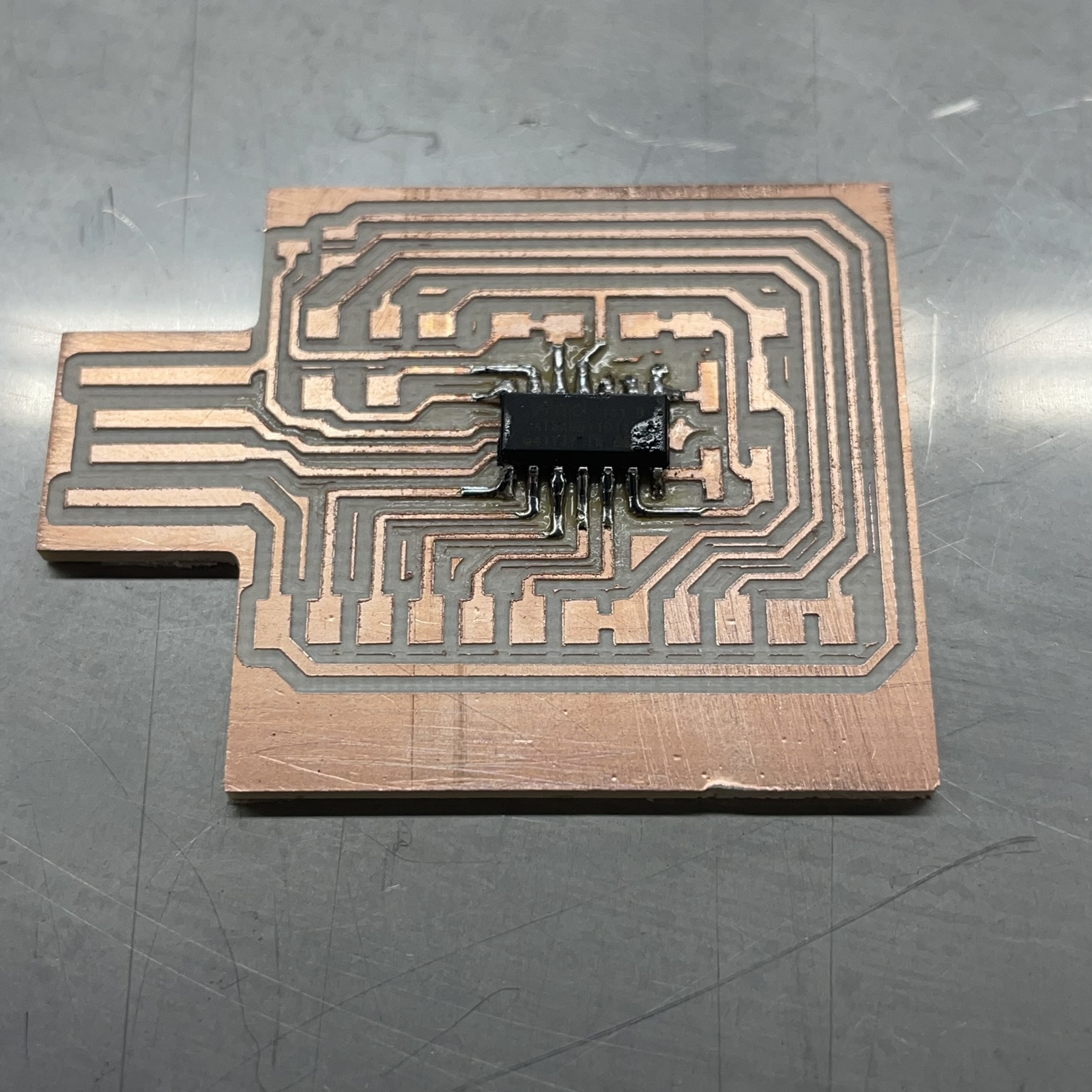
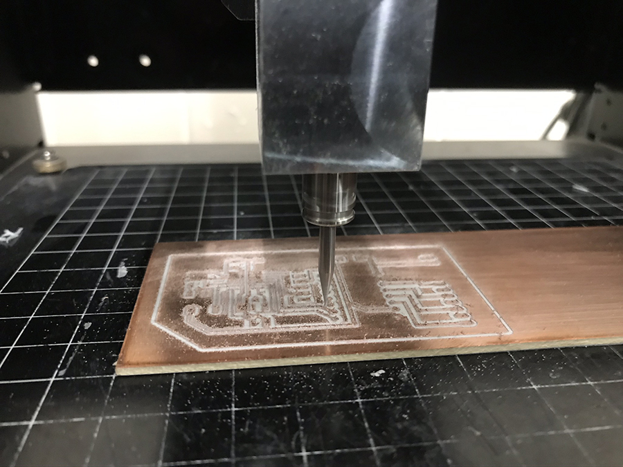
This is the milled board at the start of soldering:
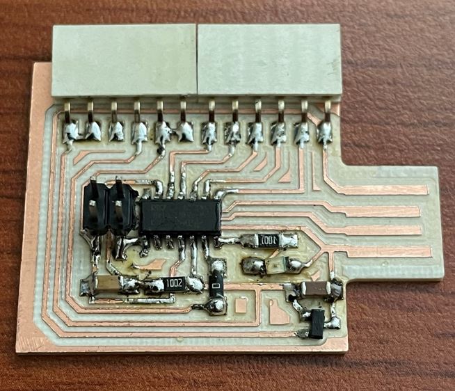
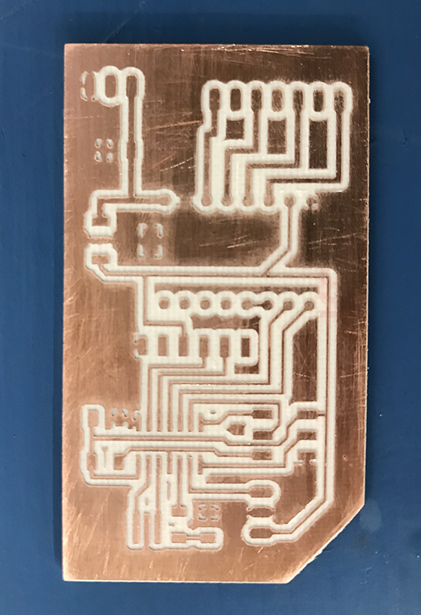
This is the finished board.
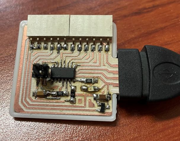
As both Adrián and Quentin did, I designed a 3d printed board "sleeve" that helps with connection.
Ultrasonic Sensor
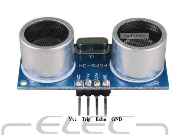
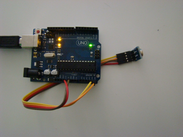
The first test for this board, was to connect it to an ultrasonic sensor. The SAMD11C datasheet will show you where to connect the sensor. This is a digital signal for the trigger and echo pins.
The sensor receives a trigger signal and sends an ultrasonic pulse to range the distance to the nearest object that reflects the sound back to it. It then measures the time it takes for the sound to come back.
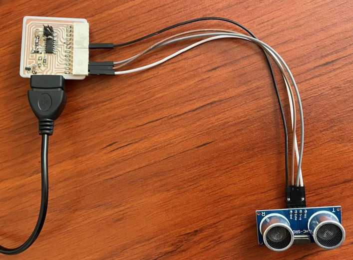
I connected it like this:
This was the code I used to program the board:
          //SAMD11C Original Code By Adrián Torres FAblab León
          //Modified by Rodrigo Shiordia Fablab CDMX
          const int EchoPin = 5;
          const int TriggerPin = 8;
          void setup() {
            Serial.begin(115200);
            pinMode(TriggerPin, OUTPUT);
            pinMode(EchoPin, INPUT);
          }
          void loop() {
            int cm = ping(TriggerPin, EchoPin);
            Serial.print("");
            Serial.println(cm);
            delay(1000);
          }
          int ping(int TriggerPin, int EchoPin) {
            long duration, distanceCm;
            digitalWrite(TriggerPin, LOW);  //to generate a clean pulse we set LOW 4us
            delayMicroseconds(4);
            digitalWrite(TriggerPin, HIGH);  //we generate Trigger (trigger) of 10us
            delayMicroseconds(10);
            digitalWrite(TriggerPin, LOW);
            duration = pulseIn(EchoPin, HIGH);  //we measure the time between pulses, in microseconds
            distanceCm = duration * 10 / 292/ 2;   //we convert distance, in cm
            return distanceCm;
          }
The arduino code does the math to change the time it takes between pulses to change it to cm. It's pretty accurate as you can see from the video.
The GUI that you see on the computer is the processing code taken also from Adrián's page.
Infrared Temperature Sensing
MLX90614
Before the COVID 19 lockdown, there were some places that had inspection posts where they used infrared thermometers to let you into a place. That's where I got the idea to measure temperature with these sensors. I found this neat part online, and after realized that it's rather popular.
The MLX90614 is an infraredd temperature sensor that works without making contact with the surface it's measuring. It is made by Melexis. Mine came on a PCB, although the datasheet does not include the PCB it's mounted on. The sensor has an integrated ADC, and hence its output is already digital. It comes pre-calibrated and will measure from -70°C up to 382°C with a 0.5° precision when compared with ambient temperature. It can have a continous output or a SMBus with I2C.
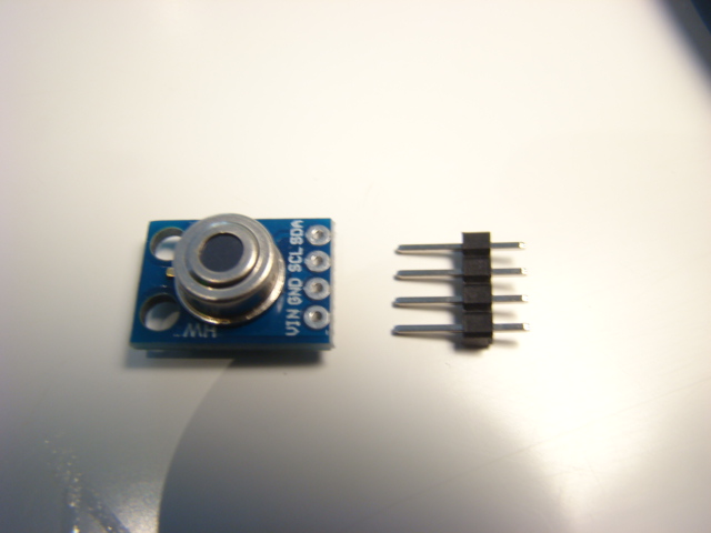
This is how the part came to me. I had to solder the pins to the interface. It has two jacks for power and two jacks for the output signal.
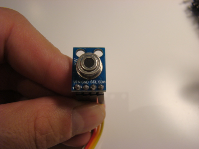
The soldered part looks like this:
Since we are on lockdown, the test is made with arduino, and at the end I will present a designed board that will use Attiny 44 or 45.
The sensor comunicates with I2C protocol, and there is a specific library for the sensor here. The library specifies that it can only use analog input pins 4 and 5, therefore you have to connect like this:
SCL goes to pin A5
SDA goes to pin A4
VIN and GNDare connected to power accordingly.
Arduino Code
The Arduino code is made much easier with the library, you only use the methods mlx.readObjectTempC() to get the number in degrees Celsius.
I modified the example file that comes with the library, so that the Serial only outputs the number in Celsius, without the rest of the text.
I took home with me the same board that I made previously So I already had an input on a board I designed, so I only needed to program it. In order to do that, I took the C code from the hello echo example, and modified it to the hello button example.
It took me a while to figure it out, but I finally got it. I had to go to the datasheet of the 44 chip and check the pins register addresses, and change the C code. I had to check which pins the button was connected on the 45 program, and which pin mine was connected to. I also had to go to both IC's datasheets and check that they both were I/O with the same functionality. They were. On the original code, the button was connected to pin PB4 and on mine, it was to PA3. The serial output was also different, but I followed the same process. This is the original hello button statements I changed:
                #define bit_delay_time 102 // bit delay for 9600 with overhead
                #define bit_delay() _delay_us(bit_delay_time) // RS232 bit delay
                #define half_bit_delay() _delay_us(bit_delay_time/2) // RS232 half bit delay

                #define input_port PORTB
                #define input_direction DDRB
                #define input_pin (1 << PB4)
                #define input_pins PINB
                #define serial_port PORTB
                #define serial_direction DDRB
                #define serial_pin_out (1 << PB2)
I changed them to this:
                #define bit_delay_time 8.5 //changedd to 115200 with overhead as in the Attiny44 example (we have the resonator).
                #define bit_delay() _delay_us(bit_delay_time) // RS232 bit delay
                #define half_bit_delay() _delay_us(bit_delay_time/2) // RS232 half bit delay

                #define input_port PORTA //input pin from button is PA3
                #define input_direction DDRA //we're using the A port pins
                #define input_pin (1 << PA3) //change the input port
                #define input_pins PINA //serial will also use port A
                #define serial_port PORTA
                #define serial_direction DDRA
                #define serial_pin_out (1 << PA1) //serial FTDI is connected to PA1
After this, I had to change the heading of the makefile to this:
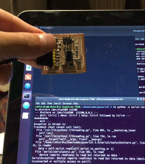
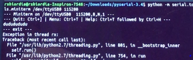
Overall it worked for like 10 seconds, and sadly, I didn't get the video for the "d" and "u" characters on the terminal. I was very satisfied when I saw those little letters, but the serial communication broke down after the first couple of tries. Other programs like the blinking program work, so my guess is that the problem lies in a short circuit on the serial communication pins. This is because I uploaded the hello echo program, and the return is gibberish. That means I know that the chip is being programmed, I know that the output pins are working and that the button is also working.
Here you can see the board returning the "d" and "u" characters to the serial port!
After this initial test, something broke down, and it stopped working. I later realized that the board had some connections come loose.
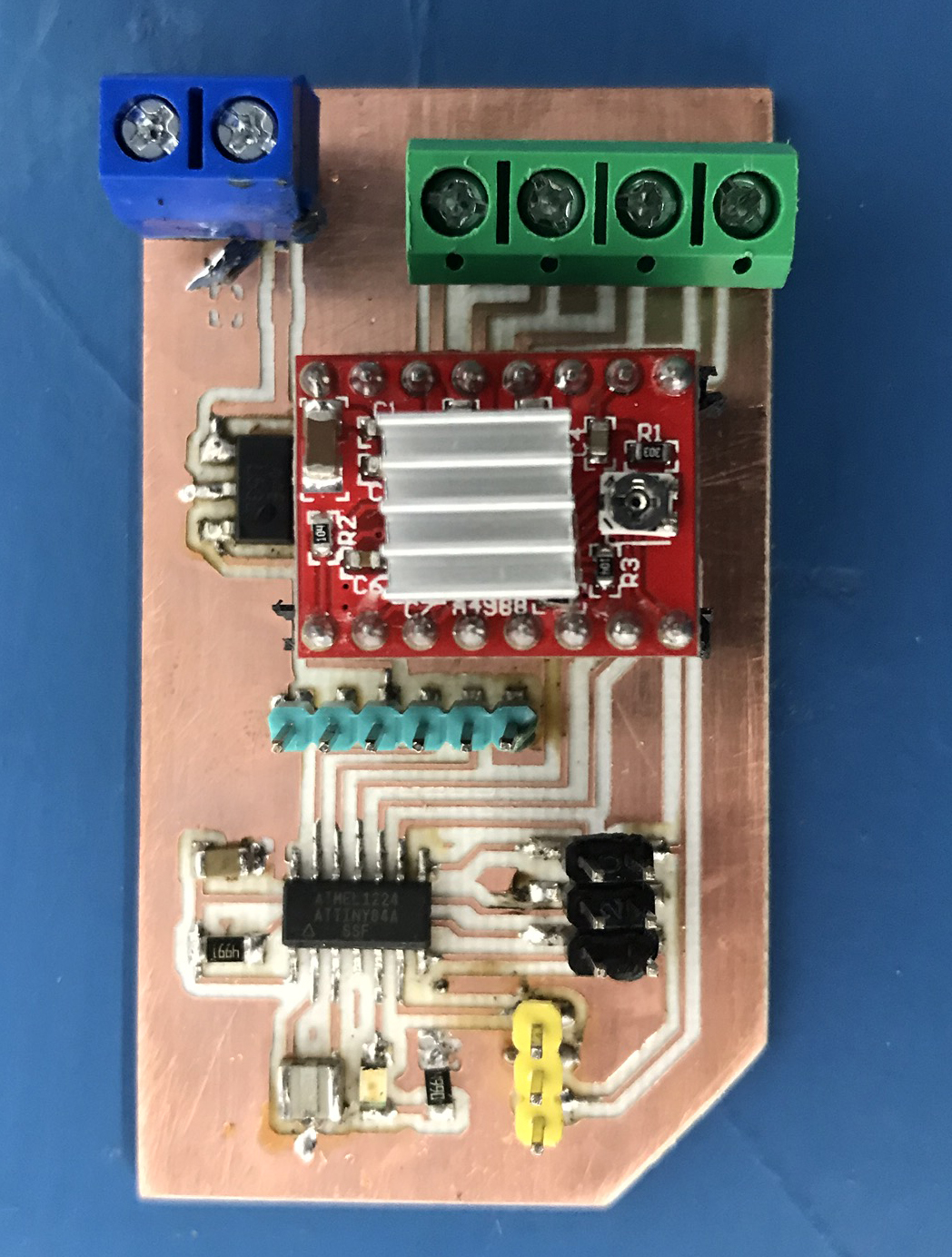
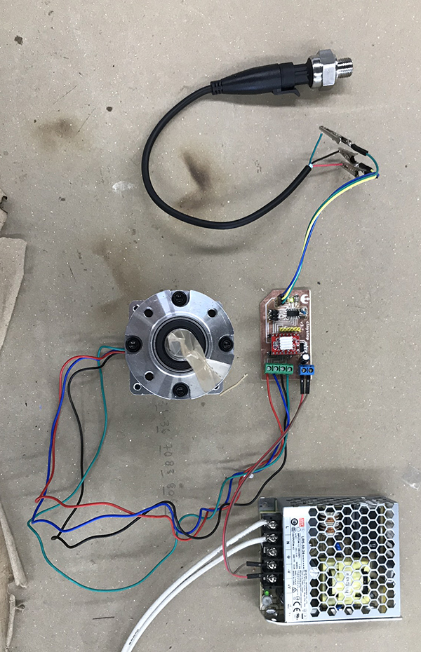
My electronic system consists of a pololu A4988 stepper driver and an ATTiny44 that controls the stepper and receives input from the pressure sensor.
I have connected the sensor to an input pin on the ATTINY44. The other pins are an LED, the step for the Pololu driver and the direction for the pololu.
The pressure sensor is connected and in my final project it will be used to speed up the extruder assembly if pressure is too high or slow it down if it's too low.
As you can see, the pressure sensor is working, and the motor as well. It actually took me 3 redesigns of the board, as well as several tries at soldering correctly.
If I blow on the pressure sensor, the motor activates.
In order to characterize the values from the sensor, I first did extensive tests on my sensor, which was done to find the values that will be used in my final project.
here is a video of that work that gave a good cutoff value of 105 for the motor.